From time to time people have compared the action of a hand plane with a machine planer on which the outfeed table is raised above the level of the infeed table by the amount of the intended cut. When normally operated, both the leading and trailing faces are supported by the tables.
It is argued that the toe of the hand plane is coplanar with the rest of the sole so this condition cannot exist. It is claimed that only the front lip of the mouth and the heel of the plane can be in contact with the wood, therefore creating a flat sole is a waste of time that could be better devoted to getting on with some real work.
However, this assumes that the plane body is rigid. Some time ago in relation to a general discussion about deflection of cast-iron plane bodies I did this practical test.
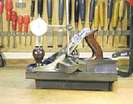
Right:A Record 05, 2" jack plane whose sole has been scraped flat. Between the sole and the cast-iron surface plate I inserted a shaving of European Beech 0.15mm (6thou) thick x 9mm (approx 5/16in) wide, one edge being level with the front lip of the mouth. This can be seen peeping out just in front of the scribing block that holds the dial gauge. At 0.15mm (6 thou), this is a fairly thick shaving for this material. It would take some effort to push the plane to produce a similar but full-width shaving.
A check with a feeler gauge revealed that at the level of the knob, the sole had been raised about 0.2mm (8 thou)
The dial gauge was set to read exactly 1mm.
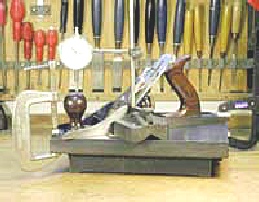
Left:The toe cramped onto the surface plate until the maximum deflection of the needle was achieved, revealing a change of about 0.15mm which, added to the original gap, reveals a deflection of about 0.35mm (or about 14thou). For fear of hearing a loud crack, I haven't yet dared to try a thicker shaving.
Now it is possible that there was some (insignificant?) compression of the beech, but whatever goes on between a moving plane and the wood, we can see that the plane can bend as it works. Just how it configures as it bends, I can't know.
Prompted by some discussion inOldTools, I've realised that I could make a decent estimate of the force produced by the cramp on the toe.
This turns out to be in the region of 60lbs which, though not impossible, was somewhat out of a reasonable practical range.
I made a mistake in using a 6thou shaving that would be much too thick for careful work such as jointing a panel.
Substituting a 1.5thou feeler gauge for the shaving, it is quite easy to bring the toe onto the surface plate with an easy squeeze between finger an thumb, hence the deflection is quite likely to occur when planing.
The estimate was made by the highly scientific means of squeezing on the toe with both thumbs to the maximum bearable pain level (mbpl) and getting a deflection of 0.1mm.
I then squeezed the platform of a bathroom scale to the same mbpl and getting a reading of 40lbs. This implies that to get the full deflection, the applied force was about 60lbs. By calculation I get the force applied by the rear cramp to be about 14lbs.
When bending the plane over a 1.5thou feeler gauge, the force on the toe only needed to be 10-12lbs.
One inch = 25.4mm (approx)
One thou =1/1000inch
I think it is a mistake to suggest that the ideal plane would be one that replicates the configuration of a machine planer (ie having the toe area higher than the rest of the sole). Possibly the above helps to show how we've all managed quite well for the last few few centuries.